How to disable windows Firewall
2016年4月17日 星期日
2015年2月25日 星期三
Dell idrac RAC0225: Sending the test mail failed
RAC0225: Sending the test mail failed.
As is usually the case, I was working on a project and was trying to understand the alerting capabilities of the Dell iDRAC7. Specifically, I was working on trying to configure SNMP, SNMP Traps, and Email alerting to keep track of critical hardware events. I keep trying with a variety of different settings, settings that I KNOW work on other systems, yet I keep getting the following message:
RAC0225: Sending the test mail failed.

I messed with various settings and tried to find a way to ping a name from the iDRAC (no, logging into it via SSH doesn’t allow you to do that).
In the end, I found that the solution that seems pretty random to me.
- On the iDRAC web interface, navigate to Overview > iDRAC Settings > Network
Under the Common Settings section, you HAVE to set a Static DNS Domain Name in the iDRAC network settings. And by setting I name, I mean ANY name. Yes, that’s right. I actually put smudwag.mud in there and suddenly my alert emails work like a charm.


This is obviously not some of Dell’s finest work, but this bug has indeed been identified by others as well. Let’s hope a future firmware release fixes this issue with iDRACs.
2014年12月6日 星期六
BGP PE-CE Routing Protocol Overview In MPLS VPNs-Part II
Introduction:
In previous document we have seen implementation of MPLS VPN BGP PE-CE routing protocol in which customer was using different AS number between their sites. In this document we will see BGP PE-CE sites implementation using same AS numbers.
If customer use the same AS number between his sites, the BGP loop prevention mechanism disallows customer sites having identical AS numbers to be linked by another AS number. In other words, routing updates from one site would be dropped when the other site receives them; therefore, connectivity cannot be established between the sites without additional configuration on the Service provider PE routers.
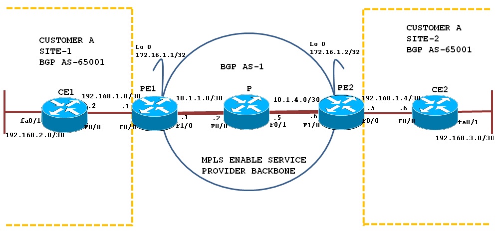
Topology Diagram:
This configuration scenario demonstrates BGP PE-CE routing for VPN sites using same BGP AS numbers. The above topology shows Customer A is using BGP AS 65001 for Site-1 and 65001 at Sites 2.
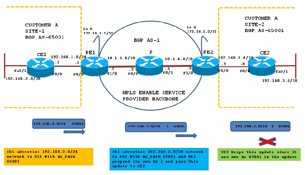
BGP loop prevention Mechanism:
When CE1 send its routing information update Over BGP VPNv4 and reached to CE2 via PE2, CE2 checks the update and finds AS 65001 in the AS-PATH ; therefore due to BGP loop prevention mechanism CE2-B rejects the 192.168.2.0/24 update from PE2 because it finds its own AS in the update.
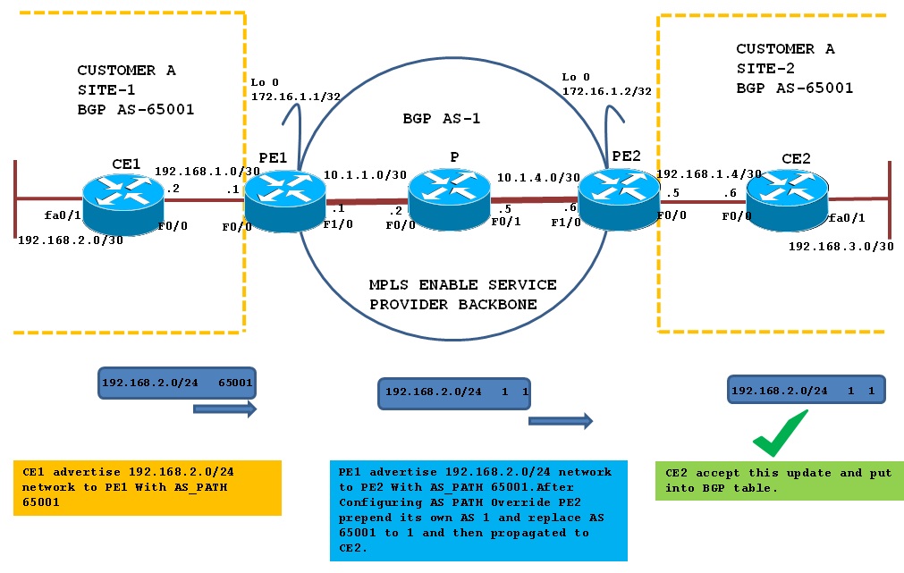
BGP AS Override feature:
To overcome above problem you can use BGP AS Override functionality on PE routers. The AS Override function causes all leading occurrences of the AS number of the receiving BGP router to be replaced with the AS number of the sending BGP router.
When you use BGP AS Override functionality, PE2 router will replace AS 65001 in the AS-PATH with its own AS number, which is 1 and send it to CE2 as shown below in diagram:
Configuration Overview:
Basic Configuration:
PE1 Router:
|
PE2 Router:
|
P Router
|
CE1 Router
|
CE2 Router
|
|---|---|---|---|---|
hostname PE1
ip cef
!
interface Loopback0
ip address 172.16.1.1 255.255.255.255
!
interface FastEthernet0/0
ip address 192.168.1.1 255.255.255.252
duplex auto
speed auto
!
interface FastEthernet1/0
ip address 10.1.1.1 255.255.255.252
speed 100
full-duplex
mpls ip
!
router ospf 100
log-adjacency-changes
network 10.1.1.1 0.0.0.0 area 0
network 172.16.1.1 0.0.0.0 area 0
!
router bgp 1
no synchronization
bgp log-neighbor-changes
neighbor 172.16.1.2 remote-as 1
no auto-summary
!
address-family vpnv4
neighbor 172.16.1.2 activate
neighbor 172.16.1.2 send-community extended
exit-address-family
!
mpls ldp router-id Loopback0
|
hostname PE2
ip cef
!
interface Loopback0
ip address 172.16.1.2 255.255.255.255
!
interface FastEthernet0/0
ip address 192.168.1.5 255.255.255.252
duplex auto
speed auto
!
interface FastEthernet1/0
ip address 10.1.1.6 255.255.255.252
speed 100
full-duplex
mpls ip
!
router ospf 100
log-adjacency-changes
network 10.1.1.6 0.0.0.0 area 0
network 172.16.1.2 0.0.0.0 area 0
!
router bgp 1
no synchronization
bgp log-neighbor-changes
neighbor 172.16.1.1 remote-as 1
neighbor 172.16.1.1 update-source Loopback0
no auto-summary
!
address-family vpnv4
neighbor 172.16.1.1 activate
neighbor 172.16.1.1 send-community extended
exit-address-family
!
mpls ldp router-id Loopback0
|
hostname P
ip cef
!
interface FastEthernet0/0
ip address 10.1.1.2 255.255.255.252
mpls ip
!
interface FastEthernet0/1
ip address 10.1.1.5 255.255.255.252
mpls ip
!
router ospf 100
log-adjacency-changes
network 10.1.1.0 0.0.0.7 area 0
|
hostname CE1
ip cef
!
interface FastEthernet0/0
ip address 192.168.1.2 255.255.255.252
!
interface FastEthernet0/1
ip address 192.168.2.1 255.255.255.0
!
router bgp 65001
no synchronization
bgp log-neighbor-changes
network 192.168.2.0 mask 255.255.255.0
neighbor 192.168.1.1 remote-as 1
no auto-summary
|
hostname CE2
ip cef
!
interface FastEthernet0/0
ip address 192.168.1.6 255.255.255.252
!
interface FastEthernet0/1
ip address 192.168.3.1 255.255.255.0
!
router bgp 65001
no synchronization
bgp log-neighbor-changes
network 192.168.3.0 mask 255.255.255.0
neighbor 192.168.1.5 remote-as 1
no auto-summary
|
We have BGP vpnv4 neighbors hip up between PE1 and PE2 can be verify as shown below:
PE1#sh ip bgp vpnv4 all summary | beg Nei
Neighbor V AS MsgRcvd MsgSent TblVer InQ OutQ Up/Down State/PfxRcd
172.16.1.2 4 1 11 11 1 0 0 00:08:43 0
PE2#sh ip bgp vpnv4 all summary | beg Nei
Neighbor V AS MsgRcvd MsgSent TblVer InQ OutQ Up/Down State/PfxRcd
172.16.1.1 4 1 11 11 1 0 0 00:08:21 0
Configuration Steps for BGP PE-CE routing:
Step 1:Define VRF Cust_A on PE Routers PE1 and PE2:
Define VRF Cust_A on PE Routers PE1 and PE2 and apply on VRF on Physical interface facing customer.
PE1#conf t
PE1(config)#ip vrf Cust_A
PE1(config-vrf)#description Customer-A
PE1(config-vrf)# rd 1:100
PE1config-vrf)# route-target both 1:100
PE1(config)#int fa0/0
PE1(config-if)#ip vrf forwarding Cust_A
PE1(config-if)#ip add 192.168.1.1 255.255.255.252
PE1(config-if)#exit
PE2#conf t
PE2(config)#ip vrf Cust_A
PE2(config-vrf)#description Customer-A
PE2(config-vrf)# rd 1:100
PE2config-vrf)# route-target both 1:100
PE2(config-vrf)#exit
PE2(config)#int fa0/0
PE2(config-if)#ip vrf forwarding Cust_A
PE2(config-if)#ip add 192.168.1.5 255.255.255.252
PE2(config-if)#exit
Step 2:Configure per VRF BGP routing context on PE routers; Define & Activate BGP CE neighbors:
Configure per VRF BGP routing for Cust_A under the BGP routing process on PE1 and PE2 and under the BGP VRF routing context mention the remote BGP CE neighbors and activated as shown below.
PE1#conf t
Enter configuration commands, one per line. End with CNTL/Z.
PE1(config)#router bgp 1
PE1(config-router)#address-family ipv4 vrf Cust_A
PE1(config-router-af)#neighbor 192.168.1.2 remote-as 65001
PE1(config-router-af)#neighbor 192.168.1.2 activate
PE1(config-router-af)#exit
PE2#conf t
Enter configuration commands, one per line. End with CNTL/Z.
PE2(config)#router bgp 1
PE2(config-router)#address-family ipv4 vrf Cust_A
PE2(config-router-af)#nei 192.168.1.6 remote-as 65001
PE2(config-router-af)#nei 192.168.1.6 activate
PE2(config-router-af)#exit
Step 3:Configure BGP AS Override command on PE1 and PE2 under BGP VRF address family:
PE1#conf t
Enter configuration commands, one per line. End with CNTL/Z.
PE1(config)#router bgp 1
PE1(config-router)#address-family ipv4 vrf Cust_A
PE1(config-router-af)#neighbor 192.168.1.2 as-override
PE1(config-router-af)#exit
PE2#conf t
Enter configuration commands, one per line. End with CNTL/Z.
PE2(config)#router bgp 1
PE2(config-router)#address-family ipv4 vrf Cust_A
PE2(config-router-af)#neighbor 192.168.1.6 as-override
PE2(config-router-af)#exit
Verification of BGP PE-CE Routing Implemention:
Step 1:Verify BGP neighbor relationship on PE1 and PE2 with CE1 and CE2 respectively:
Verify the BGP neighbor relationship between PE-CE routers. Below output shows that the BGP neighbor relationship is established between PE1 and CE1 and PE2 with CE2.
PE1#sh bgp vpnv4 unicast vrf Cust_A summary | beg Nei
Neighbor V AS MsgRcvd MsgSent TblVer InQ OutQ Up/Down State/PfxRcd
192.168.1.2 4 65001 16 16 4 0 0 00:11:32 1
PE2#sh bgp vpnv4 unicast vrf Cust_A summary | beg Nei
Neighbor V AS MsgRcvd MsgSent TblVer InQ OutQ Up/Down State/PfxRcd
192.168.1.6 4 65002 13 13 4 0 0 00:08:24 1
Step 2:Verify BGP VPNv4 routing table on PE1 and PE2:
PE1 has two prefixes in the BGP table from the remote PE router, 192.168.2.0 is learn from CE1 and 192.168.3.0 from PE2
PE1#sh bgp vpnv4 unicast vrf Cust_A
BGP table version is 4, local router ID is 172.16.1.1
Status codes: s suppressed, d damped, h history, * valid, > best, i - internal,
r RIB-failure, S Stale
Origin codes: i - IGP, e - EGP, ? - incomplete
Network Next Hop Metric LocPrf Weight Path
Route Distinguisher: 1:100 (default for vrf Cust_A)
*> 192.168.2.0 192.168.1.2 0 0 65001 i
*>i192.168.3.0 172.16.1.2 0 100 0 65002 i
Similar output is also seen on PE2
PE2#sh bgp vpnv4 unicast vrf Cust_A
BGP table version is 4, local router ID is 172.16.1.2
Status codes: s suppressed, d damped, h history, * valid, > best, i - internal,
r RIB-failure, S Stale
Origin codes: i - IGP, e - EGP, ? - incomplete
Network Next Hop Metric LocPrf Weight Path
Route Distinguisher: 1:100 (default for vrf Cust_A)
*>i192.168.2.0 172.16.1.1 0 100 0 65001 i
*> 192.168.3.0 192.168.1.6 0 0 65002 i
Step 3:Check the VRF routing table on both PE:
Check the routing table of VRF Cust_A must show routes learn from neigboring PE
PE1#sh ip route vrf Cust_A | beg Gate
Gateway of last resort is not set
192.168.1.0/30 is subnetted, 1 subnets
C 192.168.1.0 is directly connected, FastEthernet0/0
B 192.168.2.0/24 [20/0] via 192.168.1.2, 00:28:37
B 192.168.3.0/24 [200/0] via 172.16.1.2, 00:24:58
PE2#sh ip route vrf Cust_A | beg Gate
Gateway of last resort is not set
192.168.1.0/30 is subnetted, 1 subnets
C 192.168.1.4 is directly connected, FastEthernet0/0
B 192.168.2.0/24 [200/0] via 172.16.1.1, 00:28:56
B 192.168.3.0/24 [20/0] via 192.168.1.6, 00:25:31
Step 4:Verify end-to-end connectivity:
Verifying end-to-end connectivity between CE1 and CE2 by issuing a ping from CE1 to network 192.168.3.1/24 on CE2 and vice versa
CE1#ping 192.168.3.1 so 192.168.2.1
Type escape sequence to abort.
Sending 5, 100-byte ICMP Echos to 192.168.3.1, timeout is 2 seconds:
Packet sent with a source address of 192.168.2.1
!!!!!
Success rate is 100 percent (5/5), round-trip min/avg/max = 56/76/104 ms
CE2#ping 192.168.2.1 so 192.168.3.1
Type escape sequence to abort.
Sending 5, 100-byte ICMP Echos to 192.168.2.1, timeout is 2 seconds:
Packet sent with a source address of 192.168.3.1
!!!!!
Success rate is 100 percent (5/5), round-trip min/avg/max = 52/84/104 ms
訂閱:
文章 (Atom)