顯示具有 Cisco 標籤的文章。 顯示所有文章

2014年10月16日 星期四

Option 3 (10C): Multi-Hop MP-eBGP Between RR and eBGP Between ASBRs – Inter-AS MPLS VPN – The whole story (4)

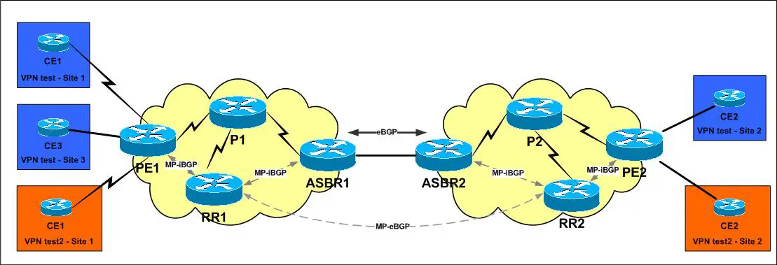
This approach is considered to be the most scalable, since when compared with Option 2(10B), the ASBRs need not learn all the VPNv4 prefixes, since now the MP-eBGP session will be established between the RRs (which already have all the VPNv4 prefixes by default) rather than the ASBRs, and the ASBRs will only be responsible of exchanging the next-hop addresses of the VPNv4 prefixes via eBGP.
Although I believe each AS having reachability to all the internal next-hops in the other AS has an implicit security concern, however practically speaking this option is normally deployed only when both autonomous systems belong to the same overall authority, such as a global Layer 3 MPLS VPN service provider with autonomous systems in different regions of the world.
NOTE In old IOS codes multihop MP-eBGP was not supported.
This option is described in the following Cisco document:
MPLS VPN Inter-AS with ASBRs Exchanging IPv4 Routes and MPLS Labels
In this approach, simply the RRs are going to exchange the VPNv4 routes, while the ASBRs will exchange the next-hops (IPv4) information piggybacked with its labels in order to complete the creation of a label switched path from the ingress local PE router to the egress remote PE router.
This is the only approach where the LSP path is not broken and the original MPLS VPN label is used all the way, since the next-hop of the VPN4 routes is not changed along the path.
According to RFC 3107 “Carrying Label Information in BGP-4″ networks configured with MP-eBGP multihop must have a label switched path (LSP) between nonadjacent routers. The neighbor x.x.x.x send-label command is required under the eBGP configuration between the ASBRs to enable the exchange of IPv4 label between the two peers plus the mpls bgp forwarding command under the ASBR-to-ASBR interface to maintain MPLS forwarding for directly connected BGP peers (be aware of the multihop eBGP between the ASBRs approach that we have described earlier).
If we were using an IGP or static routes then we could have enabled LDP on the inter-as link (like what we do with CSC using IGP and LDP), but since we are running an eBGP session over which we are advertising the next-hop addresses then we must make sure we also advertise the labels along with it using the send-label option since LDP does not advertise labels for BGP learned routes – Be aware that if there is no outgoing label for BGP next-hops then packets between Inter-AS VPNs will be discarded by the ASBRs.
NOTE When using eBGP for label exchange (using the send-label option) over a non-MPLS enabled interface, mpls bgp forwarding is automatically configured under the interface.
NOTE The neighbor x.x.x.x send-label command enables a router to use BGP to distribute MPLS labels along with the IPv4 routes to a peer router.
When BGP (eBGP and iBGP) distributes a route, it can also distribute an MPLS label that is mapped to that route. The MPLS label mapping information for the route is carried in the BGP update message that contains the information about the route (piggybacked). If the next hop is not changed, the label is preserved. When you issue the neighbor send-label command on both BPG routers, the routers advertise to each other that they can then send MPLS labels with the routes (Using AFI/SAFI: 1/4 in the Open message). If the routers successfully negotiate their ability to send MPLS labels, the routers add MPLS labels to all outgoing BGP updates.
Now to the next step, the next-hop addresses of the remote AS PEs learned via eBGP between the ASBRs must be redistributed into the IGP of the local AS via the redistribute bgp command in order for the next-hops in the remote AS to be reachable on all the local AS routers (P and PE routers). They must be advertised first by eBGP on the remote ASBR via network commands – the prefixes should be in the routing table of the their local ASBR via IGP and thus will be advertised via eBGP to the remote ASBR – or we can simply redistribute the IGP (plus filtering for security) into BGP on the local ASBR since the local AS next-hops are already learned via the local AS IGP.
Actually to exchange the loopbacks of the PE routers between the ASs we have two options (one of them is the one described earlier, but I do like the second option since most probably the ASBR will already be running iBGP with the local PE routers – most probably through a RR – thus this option would be easier configuration wise):
  1. On the local ASBR redistribute the IGP into the BGP (using a route-map for filtering only the local PEs loopbacks), then on the remote ASBR redistribute these loopbacks from BGP to the IGP (also using a route-map) – In this case the label binding will be done via LDP (since the routes are now IGP not BGP).
  2. On the local ASBR redistribute the IGP into the BGP (using a route-map for filtering only the local PEs loopbacks – or simply use network commands on the ASBR), then on the remote ASBR enable it to send IPv4 + label to all its PE routers (or most commonly to its RR and its RR should be also sending IPv4 + label to all the PE routers).
NOTE There is a major issue to take into consideration though, in the first option the label stack will be two labels (LDP Label + VPN Label), while in the second option the label stack will be three labels (LDP Label + BGP Label + VPN Label) – You need to consider the label stack depth for MTU issues.
Now to the final step, configuring the MP-eBGP peering between the RRs in the different ASes. A very crucial command to be used on both RRs is the neighbor x.x.x.x next-hop-unchangedcommand, and thus the next-hop is not changed when the VPNv4 routes are exchanged between the RRs (since we are talking about a MP-eBGP session thus the next-hop would have been changed by default), and accordingly the VPNv4 prefixes labels are not changed since the next-hop is not changed, and accordingly the remote AS uses the same MPLS VPN label as the local AS unlikeOption 2 where the next-hop was changed and new MPLS VPN labels were generated breaking the LSP.
A practical logic in using the next-hop-unchanged between the RRs lies in the fact that they should never be involved in the data/forwarding plane, and thus they must never be the next-hop for any routing updates, rather the original PE routers should be kept as the next-hops in order to be used on the data/forwarding plane – now it is very obvious why should the /32 peering (next-hop) addresses of the PE routers be advertised to the remote AS via the eBGP between the ASBRs.
Option 3 can practically have 2 sub-options, the first is the directly connected approach (eBGP peering between ASBRs using physical addresses) and the second is the multihop eBGP approach (eBGP peering between ASBRs using loopback addresses), and as described before in Option 2 this mainly depends if there are multiple circuits between the ASBRs with the need to load-balance between them for more bandwidth.
Remember that as in Option 2c (multihop MP-eBGP between ASBRs), when using multihop eBGP between the ASBRs we must enable LDP on the ASBR-to-ASBR link (or use the work around solutions described earlier in Option 2c – Check Option 2 for more details).  As I illustrated earlier I believe that since both ASBRs are not sharing an IGP thus there is no security concern in running LDP between the ASBRs since they will never insert label information learned from the other ASBR if they have no exact routes in their routing table, more over we can filter labels between the ASBRs – But for sure not having an IGP or LDP between difference SPs is the most secure situation.
Practically speaking this option is normally deployed only when both autonomous systems belongs to the same overall authority, such as a global Layer 3 MPLS VPN service provider with autonomous systems in different regions of the world, accordingly I believe that in such case enabling LDP between the ASBRs won’t be an issue, other wise it is not a recommended solution.
RR configuration example:
!
interface Loopback0
 ip address 7.7.7.7 255.255.255.255
!
interface ATM1/0.1 point-to-point
 description Connection to P1
 ip address 10.10.27.7 255.255.255.0
 ip router isis
 mpls ip
!
router isis
 net 49.0001.0070.0700.7007.00
 is-type level-2-only
 metric-style wide
 set-overload-bit
 log-adjacency-changes
 passive-interface Loopback0
!
router bgp 1
 no synchronization
 bgp log-neighbor-changes
 neighbor 1.1.1.1 remote-as 1
 neighbor 1.1.1.1 update-source Loopback0
 neighbor 3.3.3.3 remote-as 1
 neighbor 3.3.3.3 update-source Loopback0
 neighbor 8.8.8.8 remote-as 2
 neighbor 8.8.8.8 ebgp-multihop 255
 neighbor 8.8.8.8 update-source Loopback0
 no auto-summary
!
 address-family vpnv4
  neighbor 1.1.1.1 activate
  neighbor 1.1.1.1 send-community extended
  neighbor 1.1.1.1 route-reflector-client
  neighbor 3.3.3.3 activate
  neighbor 3.3.3.3 send-community extended
  neighbor 3.3.3.3 route-reflector-client
  neighbor 8.8.8.8 activate
  neighbor 8.8.8.8 send-community extended
  neighbor 8.8.8.8 next-hop-unchanged
  exit-address-family
!
ASBR configuration example:
!
interface Loopback0
 ip address 3.3.3.3 255.255.255.255
!
interface ATM1/0.1 point-to-point
 description Connection to P1
 ip address 10.10.23.3 255.255.255.0
 ip router isis
 mpls ip
!
interface ATM2/0.1 point-to-point
 description Connection to ASBR2
 ip address 10.10.34.3 255.255.255.0
 mpls bgp forwarding
!
router isis
 net 49.0001.0030.0300.3003.00
 is-type level-2-only
 metric-style wide
 log-adjacency-changes
 redistribute bgp 1 route-map ASBR
 passive-interface Loopback0
!
router bgp 1
 no synchronization
 bgp log-neighbor-changes
 network 1.1.1.1 mask 255.255.255.255
 neighbor 10.10.34.4 remote-as 2
 neighbor 10.10.34.4 send-label
 no auto-summary
!
ip prefix-list ASBR seq 1 permit 6.6.6.6/32
!
route-map ASBR permit 10
 match ip address prefix-list ASBR
!
I hope that I’ve been informative.
BR,
Mohammed Mahmoud.

Source: http://www.networkers-online.com/blog/2008/11/option-3-10c-multi-hop-mp-ebgp-between-rr-and-ebgp-between-asbrs-inter-as-mpls-vpn-the-whole-story-4/

Common Routing Problem with OSPF Forwarding Address

Introduction

This document describes the concepts and the problem associated with the Open Shortest Path First (OSPF) forwarding address. Refer to Why Are Some OSPF Routes in the Database but Not the Routing Table? for more information about troubleshooting OSPF.
The problem explained in this document is only observable with Cisco IOS® Software releases earlier than 12.1(3). The behavior of redistribution has changed in Cisco IOS Software Release 12.1(3) and later. For more details, refer to Cisco bug IDCSCdp72526 (registered customers only) . This bug has the list of Cisco IOS Software releases affected and the fixed versions. Also refer to Redistributing Connected Networks into OSPF where the change in Cisco IOS behavior is explained.

Prerequisites

Requirements

Readers of this document should have knowledge of these topics:
  • General IP routing.
  • OSPF routing protocol concepts and terms.

Components Used

The information in this document is based on these software and hardware versions:
  • Cisco 2503 routers
  • Cisco IOS® Software Release 12.2(24a) running on all the routers
The information in this document was created from the devices in a specific lab environment. All of the devices used in this document started with a cleared (default) configuration. If your network is live, make sure that you understand the potential impact of any command.

Conventions

For more information on document conventions, refer to the Cisco Technical Tips Conventions.

Description of OSPF Forwarding Address

The concept of the OSPF forwarding address was introduced to avoid extra hops when traffic is routed to an external autonomous system (AS), as shown in this figure.
10a.gif
In the figure, there are two routers in the OSPF domain that connect to the external domain. However, only Router 1 exchanges routing information with Router 100. Router 1 redistributes the information learned from Router 100 into OSPF and advertises the information to the rest of the OSPF domain. In doing this, Router 1 becomes the next hop (or forwarding address) for the information that it redistributes to the OSPF domain. When Router 2 receives a packet from the OSPF domain destined for an address in the external domain, it forwards the packet to Router 1. Router 1 then forwards it to Router 100. The forwarding address concept allows this extra hop to be avoided because it allows Router 1 to specify another router's IP address as the forwarding address. In thefigure, Router 1 can specify Router 100 as the forwarding address for external information that Router 1 redistributes into the OSPF domain. When Router 2 receives a packet from the OSPF domain destined for an address in the external domain, it forwards the packet to Router 100. The result is that the extra hop is avoided through Router 1.
The value of the forwarding address specified by the autonomous system boundary router (ASBR) (Router 1 in the previous figure) can be either 0.0.0.0 or non-zero. The 0.0.0.0 address indicates that the originating router (the ASBR) is the next hop. The forwarding address is determined by these conditions:
  • The forwarding address is set to 0.0.0.0 if the ASBR redistributes routes and OSPF is not enabled on the next hop interface for those routes. This is true in the figure if Router 1 does not have OSPF enabled on the Ethernet interface.
  • These conditions set the forwarding address field to a non-zero address:
    • OSPF is enabled on the ASBR's next hop interface AND
    • ASBR's next hop interface is non-passive under OSPF AND
    • ASBR's next hop interface is not point-to-point AND
    • ASBR's next hop interface is not point-to-multipoint AND
    • ASBR's next hop interface address falls under the network range specified in the router ospf command.
  • Any other conditions besides these set the forwarding address to 0.0.0.0.
For information on how the forwarding address is set and affects path selection refer to The Effects of the Forwarding Address on Type 5 LSA Path Selection.

Common OSPF Routing Problem Related to the Forwarding Address

10b_01.gif
The R2513 router, which only runs RIP (and may be connected to a RIP-only network), is added to the Token Ring network in thefigure. When the routes learned from R2513 are redistributed into OSPF by the ASBR (R2515), some of the routes are not installed into the routing table of some of the routers. The relevant configuration information of each of the routers is given in these tables.
hostname R2504
interface Serial0
ip address 1.1.1.2 255.255.255.0
         
interface TokenRing0
ip address 3.3.4.2 255.255.255.0
         
router ospf 1
network 1.1.1.0 0.0.0.255 area 0
network 3.0.0.0 0.255.255.255 area 1
area 1 range 3.0.0.0 255.0.0.0
hostname R2507
interface Serial0
ip address 1.1.1.1 255.255.255.0
         
interface Serial1
ip address 7.7.7.1 255.255.255.0
         
router ospf 1
network 1.1.1.1 0.0.0.0 area 0
default- information originate metric 20
         
ip route 0.0.0.0 0.0.0.0 Serial1 
hostname R2513
interface TokenRing0
ip address 3.3.4.4 255.255.255.0
       
interface ethernet 0
ip address 200.1.1.4 255.255.255.0
       
router rip
network 3.0.0.0
network 200.1.1.0
hostname R2515
interface TokenRing0
ip address 3.3.4.3 255.255.255.0
       
interface ethernet 0
ip address 3.44.66.3 255.255.255.0
       
interface ethernet 1
ip address 3.22.88.3 255.255.255.0
       
router ospf 1
redistribute rip metric 20 subnets
network 0.0.0.0 255.255.255.255 area 1
       
router rip
network 3.0.0.0

passive-interface ethernet 0
passive-interface ethernet 1
The configurations in the tables show that R2515 redistributes RIP into OSPF and that R2504 (the area border router [ABR]) creates a summarized network 3.0.0.0/8.
These are the routing tables for each of the OSPF enabled routers:
R2507# 
show ip route

Gateway of last resort is 0.0.0.0 to network 0.0.0.0
         1.0.0.0/ 24 is subnetted, 1 subnets
C          1.1.1.0 is directly connected, Serial0
         3.0.0.0/ 8 is variably subnetted, 4 subnets, 2 masks
O IA        3.0.0.0/ 8 [110/ 70] via 1.1.1.2, 00: 15: 37, Serial0
O E2        3.3.4.0/ 24 [110/ 20] via 1.1.1.2, 00: 06: 37, Serial0
O E2        3.22.88.0/ 24 [110/ 20] via 1.1.1.2, 00: 06: 37, Serial0
O E2        3.44.66.0/ 24 [110/ 20] via 1.1.1.2, 00: 06: 37, Serial0
          7.0.0.0/ 24 is subnetted, 1 subnets
C           7.7.7.0 is directly connected, Serial1
S*     0.0.0.0/ 0 is directly connected, Serial1


R2504# show ip route
Gateway of last resort is 1.1.1.1 to network 0.0.0.0
            1.0.0.0/ 24 is subnetted, 1 subnets
C             1.1.1.0 is directly connected, Serial0
            3.0.0.0/ 8 is variably subnetted, 4 subnets, 2 masks
S             3.0.0.0/ 8 is directly connected, Null0
C             3.3.4.0/ 24 is directly connected, TokenRing0
O             3.22.88.0/ 24 [110/ 11117] via 3.3.4.3, 00: 15: 16, TokenRing0
O             3.44.66.0/ 24 [110/ 11117] via 3.3.4.3, 00: 15: 16, TokenRing0
O  E2 200.1.1.0/ 24 [110/ 20] via 3.3.4.4, 00: 06: 16, TokenRing0
O* E2 0.0.0.0/ 0 [110/ 20] via 1.1.1.1, 00: 15: 16, Serial0

R2515# show ip route
 Gateway of last resort is 3.3.4.2 to network 0.0.0.0
            1.0.0.0/ 24 is subnetted, 1 subnets
 O IA         1.1.1.0 [110/ 70] via 3.3.4.2, 00: 10: 28, TokenRing0
            3.0.0.0/ 24 is subnetted, 3 subnets
 C            3.3.4.0 is directly connected, TokenRing0
 R          200.1.1.0/ 24 [120/ 1] via 3.3.4.4, 00: 00: 10, TokenRing0
 O* E2 0.0.0.0/ 0 [110/ 20] via 3.3.4.2, 00: 10: 28, TokenRing0

Network Missing from the Routing Table

R2515 has a RIP (R) derived route for network 200.1.1.0/24. R2515 is the ASBR and redistributes the RIP protocol into OSPF. R2504 learns about network 200.1.1.0/24 from R2515 and installs it in its routing table as an OSPF external type 2 (E2) route. The problem is that R2507 does not have network 200.1.1.0/24 in its routing table.
R2507 has external routes for networks 3.3.4.0/24, 3.22.88.0/24 and 3.44.66.0/24, even though all of these networks should be included in the summary of 3.0.0.0/8.
The reason these external routes show up is that the ASBR, which redistributes RIP into OSPF, has RIP running on these three subnets. It therefore redistributes the subnets as external routes into OSPF. Since these subnets are external routes, they are not summarized by the ABR (R2504). External OSPF routes can only be summarized by the ASBR. In this case, R2515. The ABR summarizes only internal OSPF routes from area 1 into area 0.
Note: With the fix of Cisco bug ID CSCdp72526 (registered customers only) , OSPF does not generate a type-5 link-state advertisement (LSA) of an overlapped external network. R2507 only has a summary inter-area route of 3.0.0.0/8. Then, R2507 installs 200.1.1.0/24 as the forwarding address and it is reachable via inter-area route 3.0.0.0/8. This is in compliance with RFC 2328leavingcisco.com.
This output shows the external LSA for network 200.1.1.0/24 in the OSPF database of R2507:
R2507# 
show ip ospf data external 200.1.1.0

       OSPF Router with ID (7.7.7.1) (Process ID 1)
       Type- 5 AS External Link States
       LS age: 72
       Options: (No TOS- capability, DC)
       LS Type: AS External Link
       Link State ID: 200.1.1.0 (External Network Number )
       Advertising Router: 3.44.66.3
       LS Seq Number: 80000001
       Checksum: 0xF161
       Length: 36
       Network Mask: /24
                   Metric Type: 2 (Larger than any link state path)
                   TOS: 0
                   Metric: 20
                   Forward Address: 3.3.4.4
                   External Route Tag: 0
OSPF allows the ASBR to specify another router as the forwarding address to external routes. In this case, the ASBR (R2515) has specified 3.3.4.4 as the forwarding address for the external network 200.1.1.0.
RFC 2328 leavingcisco.com, section 16.4 (Calculating AS external routes), states:
"If the forwarding address is non-zero, look up the forwarding address in the routing table. The matching routing table entry must specify an intra-area or inter-area path; if no such path exists, do nothing with the LSA and consider the next in the list."
In this example, the route to the forwarding address 3.3.4.4 is shown here:
R2507# 
show ip route 3.3.4.4

       Routing entry for 3.3.4.0/ 24
           Known via "ospf 1", distance 110, metric 20,type extern 2, forward metric 70
           Redistributing via ospf 1
           Last update from 1.1.1.2 on Serial0, 00: 00: 40 ago
           Routing Descriptor Blocks:
           * 1.1.1.2, from 3.44.66.3, 00: 00: 40 ago, via Serial0
              Route metric is 20, traffic share count is 1
The forwarding address of 3.3.4.4 is matched by the external route 3.3.4.0/24 instead of the inter-area summary route 3.0.0.0/8 due to the longest match rule. Because the router does not have an internal OSPF route to the forwarding address, it does not install the external route 200.1.1.0/24 in the routing table. The use of an external route to reach another external route may lead to loops. Therefore OSPF does not permit it.

Do Not Summarize on the ABR

How can you ensure that the non-zero forwarding address exists in the routing table as an intra-area or inter-area route?
The first solution is not to summarize on the ABR.
The second solution is not to configure any LSA type 3 filtering. If type 3 routes are filtered, the Forwarding address that appears on the output of the show ip ospf database external command is not reachable. This makes the external network unreachable. In this case, R2504. This causes routers in area 0 to have inter-area routes (instead of external routes) for all the specific subnets in other areas.
Use these commands to remove the summarization on the ABR:
R2504(config)# 
router ospf 1

R2504(config- router)# no area 1 range 3.0.0.0 255.0.0.0
The results of this command in the routing table on R2507 are shown here:
R2507# show ip route
       Gateway of last resort is 0.0.0.0 to network 0.0.0.0
                 1.0.0.0/ 24 is subnetted,        1 subnets
       C            1.1.1.0        is directly connected, Serial0
                 3.0.0.0/ 24 is subnetted,        3 subnets
       O IA      3.3.4.0 [110/ 70] via 1.1.1.2, 00: 00:        48, Serial0
       O IA      3.22.88.0 [110/ 80] via 1.1.1.2, 00:        00: 48, Serial0
       O IA      3.44.66.0 [110/ 80] via 1.1.1.2, 00:        00: 48, Serial0
                 7.0.0.0/ 24 is subnetted,        1 subnets
       C           7.7.7.0 is        directly connected, Serial1
       O E2 200.1.1.0/ 24 [110/ 20] via 1.1.1.2, 00: 00: 48, Serial0
       S*     0.0.0.0/ 0 is directly connected, Serial1
    
   R2507# show ip route 3.3.4.4
     Routing entry for 3.3.4.0/24
      Known via "ospf 1", distance 110, metric 70, type inter area
      Last update from 1.1.1.2 on Serial1, 00:03:52 ago
      Routing Descriptor Blocks:
      * 1.1.1.2, from 3.3.4.2, 00:03:52 ago, via Serial1
          Route metric is 74, traffic share count is 1
From the output, you can see that the address 3.3.4.4 is reachable through an inter-area route to the network 3.3.4.0/24 . The router R2507 learns the route to this network through both a Type-5 LSA and Type-3 LSA, after summarization on the ABR R2504 is removed. Since OSPF prefers an inter-area route over an external route to the same network, it installs it as an inter-area route. Sine R2507 now has an inter-area route to the forwarding address 3.3.4,4, the external network 200.1.1.0/24 is also installed in its routing table.
Note: If the NSSA ( Not So Stubby Area) is used and if the type 3 LSA filtering is done on NSSA ABR, then the same issue Forwarding Address unreachable will exist.

Prevent the Subnet from Being Redistributed into OSPF as an External Route

Another solution is to prevent the subnet 3.3.4.0 from being redistributed into OSPF as an external route, since OSPF runs on it. These configuration commands in the ASBR (R2515) create a route-map. This is used by the redistribute command to allow only network 200.1.1.0/24 to be redistributed into OSPF. The ABR (R2504) still summarizes internal OSPF routes from area 1 into area 0.
R2515# configure terminal
R2515(config)# router ospf 1
R2515(config-router)# redistribute rip metric 20 subnets route-map rip_to_ospf_filter
R2515(config-router)# exit
   
R2515(config)# 
access-list 28 permit 200.1.1.0 0.0.0.255
   
R2515(config)# 
route-map rip_to_ospf_filter permit 10
R2515(config-route-map)# 
match ip address 28

The results of this command in the routing table on R2507 are shown here:
R2507# show ip route
       Gateway of last resort is 0.0.0.0 to network 0.0.0.0
                 1.0.0.0/ 24 is subnetted,        1 subnets
       C            1.1.1.0        is directly connected, Serial0
       O IA  3.0.0.0/ 8 [110/ 70] via 1.1.1.2, 00: 07: 05, Serial0
                 7.0.0.0/ 24 is subnetted,        1 subnets
       C            7.7.7.0        is directly connected, Ethernet0
       O E2  200.1.1.0/ 24 [110/ 20] via 1.1.1.2, 00: 00: 21, Serial0
       S*      0.0.0.0/ 0 is directly connected, Ethernet0

The only external route in the routing table is 200.1.1.0/24. This network is in the routing table because the forwarding address of this external network (3.3.4.1) is covered by the summary route 3.0.0.0/8, which is an inter-area route.


Source :http://www.cisco.com/c/en/us/support/docs/ip/open-shortest-path-first-ospf/13682-10.html

2014年10月4日 星期六

Creating an MPLS VPN

Creating an MPLS VPN

By stretch | Monday, May 16, 2011 at 1:17 a.m. UTC

Today we're going to look at the configuration required to create a basic MPLS VPN servicing two customers, each with a presence at two physical sites. If you're unfamiliar with the concepts of MPLS switching and VRFs on Cisco IOS, you may want to check out a few of my past articles before continuing:
Our lab topology looks like this:
topology.png
As a review, recall that
  • P (provider) routers are ISP core routers which don't connect to customer routers and typically run only MPLS
  • PE (provider edge) routers connect to customer sites and form the edge of a VPN
  • CE (customer edge) routers exist at the edge of a customer site; they have no VPN awareness
  • an IGP running among all P and PE routers is used to support LDP and BGP adjacencies within the provider network
  • MP-BGP is run only among PE routers
  • an IGP (typically) is run between each CE router and its upstream PE router
In our lab, OSPF is already in operation as the provider network IGP. OSPF processes have also been preconfigured on the CE routers; however, these OSPF topologies will remain separate from the provider OSPF.
There are five core tasks we need to accomplish to get an MPLS VPN up and running:
  1. Enable MPLS on the provider backbone.
  2. Create VRFs and assign routed interfaces to them.
  3. Configure MP-BGP between the PE routers.
  4. Configure OSPF between each PE router and its attached CE routers.
  5. Enable route redistribution between the customer sites and the backbone.
Although plenty of CLI outputs are shown below, you may want to grab the finished router configurations if you'd like to duplicate the lab on your own.

Enable MPLS

First we need to enable MPLS on all P-P and P-PE links with the mpls ip interface command. MPLS is notenabled on any CE-facing interfaces; CE routers do not run MPLS, just plain IP routing. LDP is enabled automatically as the default label distribution protocol (versus Cisco's legacy TDP). LDP typically runs between loopback addresses not directly reachable by LDP peers, which is why it's important to configure an IGP in the core before enabling MPLS.
We can verify the configuration of MPLS interfaces with show mpls interfaces.
P1(config)# interface f0/1
P1(config-if)# mpls ip
P1(config-if)# interface f1/0
P1(config-if)# mpls ip
P1(config-if)# do show mpls interfaces
Interface              IP            Tunnel   Operational
FastEthernet0/1        Yes (ldp)     No       Yes         
FastEthernet1/0        Yes (ldp)     No       Yes         
P2(config)# interface f0/1
P2(config-if)# mpls ip
P2(config-if)# interface f1/0
P2(config-if)# mpls ip
PE1(config)# interface f1/0
PE1(config-if)# mpls ip
PE2(config)# interface f1/0
PE2(config-if)# mpls ip
LDP adjacencies can be verified with the command show mpls ldp neighbor:
P1# show mpls ldp neighbor
    Peer LDP Ident: 10.0.0.2:0; Local LDP Ident 10.0.0.1:0
    TCP connection: 10.0.0.2.45114 - 10.0.0.1.646
    State: Oper; Msgs sent/rcvd: 12/13; Downstream
    Up time: 00:02:43
    LDP discovery sources:
      FastEthernet0/1, Src IP addr: 10.0.9.2
        Addresses bound to peer LDP Ident:
          10.0.9.2        10.0.9.9        10.0.0.2        
    Peer LDP Ident: 10.0.0.3:0; Local LDP Ident 10.0.0.1:0
    TCP connection: 10.0.0.3.20327 - 10.0.0.1.646
    State: Oper; Msgs sent/rcvd: 12/12; Downstream
    Up time: 00:02:25
    LDP discovery sources:
      FastEthernet1/0, Src IP addr: 10.0.9.6
        Addresses bound to peer LDP Ident:
          10.0.9.6        10.0.0.3        

Create and Assign VRFs

Our next step is to create customer VRFs on our PE routers and assign the customer-facing interfaces to them. We need to assign each VRF a route distinguisher (RD) to uniquely identify prefixes as belonging to that VRF and one or more route targets (RTs) to specify how routes should be imported to and exported from the VRF.
We'll use a route distinguisher for each VRF in the form of <ASN>:<customer number>. For simplicity, we'll reuse the same value as both an import and export route target within each VRF (though we are free to choose a different or additional route targets if we prefer). VRF configuration must be performed on both PE routers.
PE1(config)# ip vrf Customer_A
PE1(config-vrf)# rd 65000:1
PE1(config-vrf)# route-target both 65000:1
PE1(config-vrf)# ip vrf Customer_B
PE1(config-vrf)# rd 65000:2
PE1(config-vrf)# route-target both 65000:2
PE2(config)# ip vrf Customer_A
PE2(config-vrf)# rd 65000:1
PE2(config-vrf)# route-target both 65000:1
PE2(config-vrf)# ip vrf Customer_B
PE2(config-vrf)# rd 65000:2
PE2(config-vrf)# route-target both 65000:2
The command route-target both is used as a shortcut for the two commands route-target import androute-target export, which appear separately in the running configuration.
Now we need to assign the appropriate interfaces to each VRF and reapply their IP addresses. (Assigning an interface to a VRF automatically wipes it of any configured IP addresses. Your version of IOS may or may not inform you of this when it happens.) The command show ip vrf interfaces can be used to verify interface VRF assignment and addressing.
PE1(config)# interface f0/0
PE1(config-if)# ip vrf forwarding Customer_A
% Interface FastEthernet0/0 IP address 10.0.1.1 removed due to enabling VRF Customer_A
PE1(config-if)# ip address 10.0.1.1 255.255.255.252
PE1(config-if)# interface f0/1
PE1(config-if)# ip vrf forwarding Customer_B
% Interface FastEthernet0/1 IP address 10.0.1.5 removed due to enabling VRF Customer_B
PE1(config-if)# ip address 10.0.1.5 255.255.255.252
PE1(config-if)# ^Z
PE1# show ip vrf interfaces
Interface              IP-Address      VRF                              Protocol
Fa0/0                  10.0.1.1        Customer_A                       up      
Fa0/1                  10.0.1.5        Customer_B                       up      
PE2(config)# interface f0/0
PE2(config-if)# ip vrf forwarding Customer_A
% Interface FastEthernet0/0 IP address 10.0.2.1 removed due to enabling VRF Customer_A
PE2(config-if)# ip address 10.0.2.1 255.255.255.252
PE2(config-if)# interface f0/1
PE2(config-if)# ip vrf forwarding Customer_B
% Interface FastEthernet0/1 IP address 10.0.2.5 removed due to enabling VRF Customer_B
PE2(config-if)# ip address 10.0.2.5 255.255.255.252
PE2(config-if)# ^Z
PE2# show ip vrf interfaces
Interface              IP-Address      VRF                              Protocol
Fa0/0                  10.0.2.1        Customer_A                       up      
Fa0/1                  10.0.2.5        Customer_B                       up      

Configure MP-BGP on the PE Routers

This is where things start to get interesting. In order to advertise VRF routes from one PE router to the other, we must configure multiprotocol BGP (MP-BGP). MP-BGP is a little different from legacy BGP in that it supports multiple address families (e.g. IPv4 and IPv6) over a common BGP adjacency. It also supports the advertisement of VPN routes, which are longer than normal routes due to the addition of a 64-bit route distinguisher (which we assigned under VRF configuration).
MP-BGP runs only on the PE routers: P routers rely entirely on the provider IGP and MPLS to forward traffic through the provider network, and CE routers have no knowledge of routes outside their own VRF.
Minimal MP-BGP configuration is pretty straightforward. Both PE routers exist in BGP AS 65000.
PE1(config)# router bgp 65000
PE1(config-router)# neighbor 10.0.0.4 remote-as 65000
PE1(config-router)# neighbor 10.0.0.4 update-source loopback 0
PE1(config-router)# address-family vpnv4
PE1(config-router-af)# neighbor 10.0.0.4 activate
PE2(config)# router bgp 65000
PE2(config-router)# neighbor 10.0.0.3 remote-as 65000
PE2(config-router)# neighbor 10.0.0.3 update-source loopback 0
PE2(config-router)# address-family vpnv4
PE2(config-router-af)# neighbor 10.0.0.3 activate
If we look at the running configuration of the BGP process on either PE router, we notice that a bit more configuration than we provided has appeared:
PE1# show running-config | section router bgp
router bgp 65000
 no synchronization
 bgp log-neighbor-changes
 neighbor 10.0.0.4 remote-as 65000
 neighbor 10.0.0.4 update-source Loopback0
 no auto-summary
 !
 address-family vpnv4
  neighbor 10.0.0.4 activate
  neighbor 10.0.0.4 send-community extended
 exit-address-family
 !
 address-family ipv4 vrf Customer_B
  no synchronization
 exit-address-family
 !
 address-family ipv4 vrf Customer_A
  no synchronization
 exit-address-family
In addition to our VPNv4 address family, address families for the two customer VRFs have been created automatically. Also, support for extended community strings has been added to the VPNv4 neighbor configuration.
Verify that the MP-BGP adjacency between PE1 and PE2 was formed successfully with the commandshow bgp vpnv4 unicast all summary:
PE1# show bgp vpnv4 unicast all summary
BGP router identifier 10.0.0.3, local AS number 65000
BGP table version is 1, main routing table version 1

Neighbor        V    AS MsgRcvd MsgSent   TblVer  InQ OutQ Up/Down  State/PfxRcd
10.0.0.4        4 65000      12      12        1    0    0 00:06:05        0
Currently, there are no routes in the BGP table, because we have not specified anything to be advertised or redistributed, but we'll get to that after this next step.

Configure PE-CE OSPF

We just configured MP-BGP between the two PE routers. Now, let's configure an IGP between each PE router and its attached CE routers to exchange routes with the customer sites. We're going to use OSPF for this lab, but we could just as easily use another IGP like EIGRP or RIP.
Single-area OSPF has already been configured on the CE routers; all CE interfaces are in area 0. Remember that although we're using OSPF between each of the CE routers and its upstream PE router, these OSPF processes are isolated from the provider OSPF topology. The overall routing topology will look like this:
routing_topology.png
The provider OSPF process has already been configured on the PE routers as process 1. We'll configure anadditional OSPF process for each CE router on each PE router. Each PE router will then have three OSPF processes total: one for the provider network, and one for each CE router. Whereas the provider OSPF process exists in the global routing table, the two CE processes will each be assigned to their respective customer VRFs.
PE1(config)# router ospf 2 vrf Customer_A
PE1(config-router)# router-id 10.0.1.1
PE1(config-router)# interface f0/0
PE1(config-if)# ip ospf 2 area 0
PE1(config-if)# router ospf 3 vrf Customer_B
PE1(config-router)# router-id 10.0.1.5
PE1(config-router)# interface f0/1
PE1(config-if)# ip ospf 3 area 0
PE2(config)# router ospf 2 vrf Customer_A
PE2(config-router)# router-id 10.0.2.1
PE2(config-router)# interface f0/0
PE2(config-if)# ip ospf 2 area 0
PE2(config-if)# router ospf 3 vrf Customer_B
PE2(config-router)# router-id 10.0.2.5
PE2(config-router)# interface f0/1
PE2(config-if)# ip ospf 3 area 0
We should see each PE router form an OSPF adjacency with both of its attached CE routers, and the customer routes should appear in the VRF tables on the PE routers.
PE1# show ip route vrf Customer_A

Routing Table: Customer_A
...

172.16.0.0/16 is variably subnetted, 2 subnets, 2 masks
O       172.16.1.0/24 [110/11] via 10.0.1.2, 00:04:21, FastEthernet0/0
O       172.16.0.1/32 [110/11] via 10.0.1.2, 00:04:21, FastEthernet0/0
     10.0.0.0/30 is subnetted, 1 subnets
C       10.0.1.0 is directly connected, FastEthernet0/0
PE1# show ip route vrf Customer_B

Routing Table: Customer_B
...

172.17.0.0/16 is variably subnetted, 2 subnets, 2 masks
O       172.17.1.0/24 [110/11] via 10.0.1.6, 00:03:03, FastEthernet0/1
O       172.17.0.1/32 [110/11] via 10.0.1.6, 00:03:04, FastEthernet0/1
     10.0.0.0/30 is subnetted, 1 subnets
C       10.0.1.4 is directly connected, FastEthernet0/1

Configure Route Redistribution

We're almost done! We have our MPLS and MP-BGP backbone up and running, and our CE routers are sending routes to our PE routers within their VRFs. The last step is to glue everything together by turning on route redistribution from the customer-side OSPF processes into MP-BGP and vice versa on the PE routers.
First we'll configure redistribution of CE routes in each VRF into MP-BGP. This is done under the BGP IPv4 address family for each VRF.
PE1(config)# router bgp 65000
PE1(config-router)# address-family ipv4 vrf Customer_A
PE1(config-router-af)# redistribute ospf 2
PE1(config-router-af)# address-family ipv4 vrf Customer_B
PE1(config-router-af)# redistribute ospf 3
PE2(config)# router bgp 65000
PE2(config-router)# address-family ipv4 vrf Customer_A
PE2(config-router-af)# redistribute ospf 2
PE2(config-router-af)# address-family ipv4 vrf Customer_B
PE2(config-router-af)# redistribute ospf 3
This enables redistribution of OSPF routes into BGP for transport across the provider network between the two sites. We can verify that the routes learned from the customer sites (the 172.16.0.0/16 and 172.17.0.0/16 networks) now appear in the BGP tables for their respective VRFs.
PE1# show ip bgp vpnv4 vrf Customer_A
...

Network          Next Hop            Metric LocPrf Weight Path
Route Distinguisher: 65000:1 (default for vrf Customer_A)
*> 10.0.1.0/30      0.0.0.0                  0         32768 ?
*>i10.0.2.0/30      10.0.0.4                 0    100      0 ?
*> 172.16.0.1/32    10.0.1.2                11         32768 ?
*>i172.16.0.2/32    10.0.0.4                11    100      0 ?
*> 172.16.1.0/24    10.0.1.2                11         32768 ?
*>i172.16.2.0/24    10.0.0.4                11    100      0 ?
PE1# show ip bgp vpnv4 vrf Customer_B
...

Network          Next Hop            Metric LocPrf Weight Path
Route Distinguisher: 65000:2 (default for vrf Customer_B)
*> 10.0.1.4/30      0.0.0.0                  0         32768 ?
*>i10.0.2.4/30      10.0.0.4                 0    100      0 ?
*> 172.17.0.1/32    10.0.1.6                11         32768 ?
*>i172.17.0.2/32    10.0.0.4                11    100      0 ?
*> 172.17.1.0/24    10.0.1.6                11         32768 ?
*>i172.17.2.0/24    10.0.0.4                11    100      0 ?
The last step is to complete the redistribution in the opposite direction: from BGP into the customer OSPF processes. If you're accustomed to route redistribution, there's nothing new here. (We don't have to specify any VRF information in the redistribution statement because each customer OSPF process is already assigned to a VRF.)
PE1(config)# router ospf 2
PE1(config-router)# redistribute bgp 65000 subnets
PE1(config-router)# router ospf 3 
PE1(config-router)# redistribute bgp 65000 subnets
PE2(config)# router ospf 2
PE2(config-router)# redistribute bgp 65000 subnets
PE2(config-router)# router ospf 3
PE2(config-router)# redistribute bgp 65000 subnets

Testing and Confirmation

If has gone well, we should now have end-to-end connectivity between the CE routers within each VRF. Both routers for each customer should now have complete routing tables. Here are customer A's routes:
CE1A# show ip route
...

172.16.0.0/16 is variably subnetted, 4 subnets, 2 masks
C       172.16.1.0/24 is directly connected, Loopback1
C       172.16.0.1/32 is directly connected, Loopback0
O IA    172.16.2.0/24 [110/21] via 10.0.1.1, 00:03:50, FastEthernet0/0
O IA    172.16.0.2/32 [110/21] via 10.0.1.1, 00:03:50, FastEthernet0/0
     10.0.0.0/30 is subnetted, 2 subnets
O IA    10.0.2.0 [110/11] via 10.0.1.1, 00:03:50, FastEthernet0/0
C       10.0.1.0 is directly connected, FastEthernet0/0
CE2A# show ip route
...

172.16.0.0/16 is variably subnetted, 4 subnets, 2 masks
O IA    172.16.1.0/24 [110/21] via 10.0.2.1, 00:02:49, FastEthernet0/0
O IA    172.16.0.1/32 [110/21] via 10.0.2.1, 00:02:49, FastEthernet0/0
C       172.16.2.0/24 is directly connected, Loopback1
C       172.16.0.2/32 is directly connected, Loopback0
     10.0.0.0/30 is subnetted, 2 subnets
C       10.0.2.0 is directly connected, FastEthernet0/0
O IA    10.0.1.0 [110/11] via 10.0.2.1, 00:02:49, FastEthernet0/0
You may notice that OSPF routes sent between two sites belonging to the same customer appear as inter-area routes. Remember that although OSPF area 0 is being used at both sites, each site exists as a separate link-state topology connected by the MPLS VPN.
We should be able to ping from one CE router to the other. (Remember that we don't need to specify a VRF when doing so because CE routers have no knowledge that they're in a VRF.)
CE1A# ping 172.16.0.2

Type escape sequence to abort.
Sending 5, 100-byte ICMP Echos to 172.16.0.2, timeout is 2 seconds:
!!!!!
Success rate is 100 percent (5/5), round-trip min/avg/max = 12/21/32 ms
We can perform a traceroute to verify the path taken as well as the MPLS labels used to traverse the provider network.
CE1A# traceroute 172.16.0.2

Type escape sequence to abort.
Tracing the route to 172.16.0.2

1 10.0.1.1 4 msec 4 msec 8 msec
  2 10.0.9.5 [MPLS: Labels 19/22 Exp 0] 16 msec 12 msec 24 msec
  3 10.0.9.2 [MPLS: Labels 19/22 Exp 0] 24 msec 20 msec 16 msec
  4 10.0.2.1 [MPLS: Label 22 Exp 0] 20 msec 16 msec 24 msec
  5 10.0.2.2 16 msec *  36 msec
Here's a packet capture of the above traceroute if you're interested in how the MPLS label information is returned. And again, here are the the finished router configurations if you'd like to replicate the lab yourself.


Source:  http://packetlife.net/blog/2011/may/16/creating-mpls-vpn/

2014年9月12日 星期五

CCIE SP 350-029 Question 380-421

CCIE SP Written Exam (Version 3.0)


Number: 350-029
Passing Score: 790
Time Limit: 120 min
File Version: 421Q+69


QUESTION 381
Which two statements about 6RD are true? (Choose two.) 
A. The 6RD customer edge device forwards all packets to the 6RD border relay. 
B. The 6RD customer edge device can forward packets destined to other 6RD customer edge devices outside the local 6RD domain without traversing the 6RD
border relay. 
C. Packets between 6RD customer edge devices in the same 6RD domain do not need to traverse the 6RD border relay. 
D. Packets received from a 6RD domain can easily be identified as such on the IPv6 Internet. 
E. The entry point into the local 6RD domain is deterministic. 


Correct Answer: CE


QUESTION 382
Which statement about implementing the Cisco IPv6 provider Edge Router over MPLS is true? 
A. 6PE feature is supported over tunnels other than RSVP-TE tunnels. 
B. Core MPLS routers are supporting IPv6 only. 
C. 6PE feature is not supported over tunnels other than RSVP-TE tunnels. 
D. Core MPLS routers are supporting IPv4 only. 


Correct Answer: C


QUESTION 383
Which are three advantages of PPPoA implementation? (Choose three) 
A. NAP and NSP provide secure access to corporate gateways without managing end-to-end PVCs. NAP and NSP use Layer 3 routing, Layer 2 Forwarding, or Layer 2 Tunneling Protocol tunnels. Hence, they can scale their business models for selling wholesale service. 
B. The NSP can oversubscribe by deploying idle and session timeouts using an industry standard RADIUS server for each subscriber. 
C. Only a single session per CPE on one virtual channel (VC). The username and password are configured on the CPE, so all users behind the CPE for that
particular VC can access only one set of services. Users cannot select different sets of services, although using multiple VCs and establishing different PPP
session on different VCs is possible. 
D. If a single IP address is provided to the CPE, and NAT or PAT is implemented, certain pplications such as IPTV, which embed IP information in the payload,
well not work. Additionally, if an IP subnet feature is used, an IP address also has to be reserved for the CPE. 
E. PPPoA can use the features on the Cisco Service Selection Gateway (SSG) 


Correct Answer: ABE


QUESTION 384
Select the 3 best answers describing operation and configuration of Frame-Relay Inverse ARP. 
A. Dynamic address mapping uses Frame Relay Inverse ARP to request the next-hop protocol address for a specific connection on its known DLCI. 
B. Responses to Inverse ARP requests are entered in an address-to-DLCI mapping table on the router or access server which is used to supply the next-hop
protoco address or the DLCI for outgoing traffic. 
C. Inverse ARP is enabled by default for all protocols enabled on the physical interface. 
D. Inverse ARP is configured using the following command under the Interface configuration 'frame-relay mapdlci (dlci number) protocol protocol-address'. 
E. Inverse ARP in Frame-Relay is synonymous of ARP in Ethernet. 


Correct Answer: ABC


QUESTION 385
Which three attribute-value pairs (AVPs) must be present in L2TPv3 ICRQ messages? (Choose three.) 
A. PW capabilities list 
B. Message type 
C.Assigned control connection ID 
D. PW type 
E. Remote session ID 
F. Hostname 


Correct Answer: BDE


QUESTION 386
Which four services use the inner labels of an MPLS label stack? (Choose four) 
A. MPLS VPN 
B. switching path in MPLS core 
C. Cisco MPLS Traffic Engineering and Fast Reroute 
D. MPLS over ATM 
E. VPN over Traffic Engineering core 
F. any transport over MPLS 


Correct Answer: ACEF


QUESTION 387
The Attribute field within the IS-IS LSP header contains which of the following flags? (Choose four) 
A. IS-Type 
B. Overload (LSPDBOL) 
C. Pseudonode (PN) 
D. Attached (ATT) 
E. Fragment (Frag-Nr) 
F. Partition (P) 


Correct Answer: ABDF


QUESTION 388

Refer to the exhibit. 


Inbound Infrastructure ACLs are configured to protect the SP network. Which three types of traffic should be filtered in the infrastructure ACLs? (Choose three.) 
A. traffic from a source with an IP address that is within 239.255.0.0/16 
B. FTP traffic destined for internal routers 
C. IPsec traffic that at an internal router 

D. traffic from a source with an IP address that is within 162.238.0.0/16 
E. EBGP traffic that peers with edge routers 


Correct Answer: ABD


QUESTION 389
Which four of these statements are restrictions for Frame Relay PVC bundles with QoS support for IP and MPLS? (Choose four) 
A. A PVC bundle will not come up unless all the precedence, DSCP, and EXP levels are configured in the bundle. 
B. A PVC bundle can perform precedence and DSCP matching at the same time 
C. A PVC bundle may contain no more than sixteen PVCs 
D. A PVC can be in only one PVC bundle 
E. A PVC bundle cannot perform precedence and DSCP matching at the same time. 
F. A PVC bundle may contain no more than eight PVCs. 


Correct Answer: ADEF


QUESTION 390
Option 10C is an implementation of Inter-AS MPLS VPN. Which two statements about Option 10C are true? (Choose two.) 
A. Great scalability is offered 
B. Route Target Rewrite must be configured on ASBRs 
C. Multihop EBGP is utilized between route reflectors 
D. Multihop EBGP is utilized between ASBRs 
E. The ASBRs hold VPNv4 routes 


Correct Answer: AC


QUESTION 391
Which two statements best describe the signalling requirements of virtual circuit setup of VPLS and exchange of reachability information (MAC addresses)? 
A. Cisco VPLS does not require the exchange of reachability (MAC addresses) information via a signaling protocol. This information is learned from the data
plane using standard address learning, aging, and filtering mechanisms defined for Ethernet bridging. 
B. Cisco VPLS uses directed LDP as a signalling protocol to exchange reachability (MAC addresses) information to avoid maintanance of ARP cache. 
C. In Cisco VPLS the virtual circuit setup uses Multi-Protocol BGP as autodiscovery and signaling mechanism. Using BGP allows BPDUs to be propagated
across VPLS in a scaleable fashion. 
D. In Cisco VPLS the virtual circuit setup uses the same LDP signaling mechanism defined for point-to-point services. Using a directed LDP session, each
provider edge advertises a virtual circuit label mapping that is used as part of the label stack imposed on the Ethernet frames by the ingress provider edge during packet forwarding. 


Correct Answer: AD


QUESTION 392
In relation to MPLS Multicast VPN, which three statements about multicast distribution (MDT) groups are true? (Choose three) 
A. Default MDT groups are used for PIM control traffic, low-bandwidth sources, and flooding of sparse mode traffic. 
B. MDTs are built in customer networks 
C. Data MDT groups are used for high-bandwidth sources to reduce replication to uninterested PEs. 
D. MDTs are built in provider networks 
E. The number of MDTs depends on PIM modes of MDT groups. 


Correct Answer: CDE


QUESTION 393
Which two statements about RPF checks in Multicast Source Discovery Protocol (MSDP) are true? (Choose two) 
A. RPF check should be done against the route to the source of the corresponding PIM-SM domain. 
B. Checking session advertisement (SA) messages causes messages looping. 
C. The RPF check ensures that there is a working redundancy for anycast RPs. 
D. RPF check should be done against the route to the RP of the PIM-SM domain that originated the SA. 
E. It prevents message looping, and session advertisement (SA) messages must be RPF checked. 


Correct Answer: DE


QUESTION 394
Select 3 AVPs (Attribute-Value Pair) which MUST be present in the ICRQ: 
A. Called Number 
B. Call Serial Number 
C. Message Type 
D. Calling Number 
E. Assigned Session ID 


Correct Answer: BCE


QUESTION 395
Which three statements about L2TPv3 are true? (Choose three) 
A. L2TPv3 Frame Relay support includes only 32-bit DLCI addressing. 
B. L2TPv3 sessions do not support Frame Relay LMI interworking. 
C. Multipoint DLCI is not supported. 
D. To use DCE or a Network-to-Network Interface on a Frame Relay port, you must configure the frame-relayswitching command. 
E. L2TPv3 feature does not support Frame Relay extended addressing. 


Correct Answer: CDE


QUESTION 396
Which three options are restrictions for MPLS VPN BGP Local Convergence? (Choose three.) 
A. The MPLS VPN BGP Local Convergence feature affects only traffic that is exiting the VPN. Therefore, it cannot fully protect traffic end-to-end by itself. 
B. This link protection can be initiated during a HA SSO. But links that were configured with this protection before the switchover begins remain protected after the
switchover. 
C. The MPLS VPN BGP Local Convergence feature for IPv4/IPV6 supports the eBGP, RIP, EIGRP,OSPF, and dynamic routing protocols. 
D. Any next-hop core tunneling technology that is supported by BGP is also supported for protection, including MPLS, L2TPv3, and IP/GRE. CSC protocol
between the PE and CE is also supported. Interautonomous system option A (back-to-back VRF) is supported because it is essentially the same as performing
the PE-CE link protection in both autonomous systems. However, interautonomous system options B and C protection are not supported. 
E. If you perform an in-service software downgrade from an image that does include this link protection to an image that does not support this feature, active
protection is halted when BGP routes are refreshed. 


Correct Answer: ADE


QUESTION 397
Identify the differences of option 10A, as opposed to option 10C, for interAS vpn offerings For option 10A? (Choose three). 
A. Greater scalability is offered 
B. The ASBR holds VPNv4 routes 
C. Relative technical simplicity is offered 
D. Lower relative security is offered 
E. Multihop eBGP between ASBRs is utilized 
F. Better suitability for InterProvider VPNs is provided 


Correct Answer: BCF


QUESTION 398
Which of the following descriptions about uRPF loose mode is correct? (Choose two). 
A. It is typically used on point-to-point interfaces where the same interface is used for both directions of packet flows; if the source address has a return route in
the FIB table, it is then checked against the adjacency table to ensure the same interface receiving the packet is the same interface used for the return path 
B. If a packet fails the uRPF loose mode check, the packet is then transmitted and creates a log message 
C. It is typically used on multipoint interfaces or on routers where asymmetrical routing is used (packets are received on one interface but the return path is not on
the same interface); loose mode verifies a source address by looking in forwarding information base(FIB). 
D. If a packet fails the uRPF loose mode check, the packet is then dropped 


Correct Answer: CD


QUESTION 399
Which statement about MPLS Traffic Engineering class-based tunnel selection (CBTS) is not true? 
A. Local mechanism is at the middle-point router. 
B. EXP selection is between multiple tunnels to the same destination 
C. Bundle members are configured with EXP values to carry. 
D. The tunnel selection is configured on the tunnel master. 
E. The tunnel master bundles the tunnel members 


Correct Answer: A


QUESTION 400
Option 10A (back-to-back VRF) is an implementation of inter-AS MPLS VPN. Which of four statements about option 10A are not true? (Choose four.) 
A. MPLS is required between the ASBRs. 
B. ASBR must hold all routing information. 
C. It is a scalable solution. 
D. It is a simple solution. 
E. MP-EBGP is used to exchange routes between ASBRs. 


Correct Answer: ACDE


QUESTION 401
In which of the following lists of APS Action Requests is the priority correctly arranged from lowest to highest? 
A. Wait-to-Restore, Manual Switch, Forced Switch, Lockout of Protection 
B. Wait-to-Restore, Forced Switch, Manual Switch, Lockout of Protection. 
C. Manual Switch, Wait-to-Restore, Lockout of Protection, Forced Switch. 
D. Lockout of Protection, Forced Switch, Manual Switch, Wait-to-Restore 
E. Lockout of Protection, Manual Switch, Forced Switch, Wait-to-Restore 
F. Wait-to-Restore, Manual Switch, Lockout of Protection, Forced Switch 


Correct Answer: A


QUESTION 402
In the Carrier Supporting Carrier (CsC) feature, which two protocols run between CSC-PE and CSC-CE. (Choose two) 
A. IGP and RSVP 
B. EBGPv4 with a sending community 
C. IGP and EBGPv4 
D. IGP and LDP 
E. EBGPv4 with a sending label 


Correct Answer: DE


QUESTION 403
Which two statements about DS-Lite are true? (Choose two.) 
A. IPv4 packets are carried over IPv6 tunnels to the LSN while IPv6 traffic is forwarded natively. 
B. Ipv6 packets are carried over IPv4 tunnels to the LSN while IPv4 traffic is forwards natively. 
C. The LSN performs NAT44 on private IPv4 source addresses. 
D. DS-Lite does not perform any address translation. 


Correct Answer: AC


QUESTION 404
Which three things are the building blocks of the Cisco VPLS architecture? (Choose three) 
A. VLAN Trunk Protocol (VTP) 
B. State Synchronization Protocol (SSP) 
C. L2VPN 
D. Ethernet Virtual Switch Interface (VSI) 
E. Label Distribution Protocol (LDP) 


Correct Answer: CDE


QUESTION 405
Which two statements about OSPF IPv6 routing are true? (Choose two) 
A. It requires OSPF version 3. 
B. automatically detects neighbors over NHMA interfaces 
C. It supports encryption using 
D. It uses LSA type 9 
E. It uses LSA type 8 


Correct Answer: AE


QUESTION 406
Which three configuration options are available for configuring the l2tp-class command in L2TPv3? (Choose three) 
A. TCP port 
B. authentication 
C. IP DF bit 
D. retransmit retries 
E. sequencing 
F. hostname 


Correct Answer: BDF


QUESTION 407
Which two statements about the bgp deterministic-med and bgp always-compare-med commands are true? (Choose two) 
A. The bgp deterministic-med command is used to influence the BGP route selection process to cause the MED attribute to have higher precedence over the AS
path length 
B. The bgp always-compare command is used to influence the BGP route selection process to cause the MED attribute to have higher precedence over the AS
path system. 
C. Enabling the bgp deterministic-med command ensures the comparison of the MED variable when choosing routes advertised by different peers in the same
autonomous system. 
D. Enabling the bgp always-compare-med command ensures the comparison of the MED variable for paths from neighbors in different autonomous systems. 
E. The bgp deterministic-med and bgp always-compare-med commands are enabled by defult. 


Correct Answer: CD


QUESTION 408
Which three options are functions of the Cisco Service Control Engine? (Choose three.) 
A. intelligent inspection and control of IP packets 
B. application of session-level bandwidth shaping 
C. provisioning of access aggregation 
D. per-subscriber bandwidth management 
E. Implementation of VPN services 


Correct Answer: ABD


QUESTION 409
All secure domain routers (SDRs) have shared attribute and resources. Which three resources are shared all SDRs? (Choose three.) 
A. privilege-level configuration 
B. fabric cards 
C. SNMP traps 
D. admin-level configuration 
E. exec-level configuration 


Correct Answer: BCD


QUESTION 410
Which three statements about bidirectional PIM are true? (Choose three) 
A. Traffic for a bidirectional group flows along the one shared tree and simultaneously utilizes multiple paths in a redundant network topology. 
B. It does not require any traffic signaling in the protocol 
C. Membership to a bidirectional group is signaled using explicit Join messages. 
D. It maintains source-specific forwarding state. 
E. It reduces memory, bandwidth, and CPU requirements 


Correct Answer: BCE


QUESTION 411
Which two statements are true about DPT/RPR? 
A. DPT/RPR uses a bi-directional ring consisting of two symmetric counter rotating fibre rings. 
B. DPT/RPR is defined in the IEEE 802.17 standard and it uses Token Bucket system to avoid collisions on the fiber. 
C. DPT/RPR can be deployed in the Core of the SP networks where point-to-point POS links are used to make best use of the Bandwidth. 
D. In DPT/RPR rings, data packets can be sent in one direction (downstream) and the corresponding control packets in the opposite direction (upstream), thus
using both fibres concurrently to maximize bandwidth. 


Correct Answer: AD


QUESTION 412
What are three common reasons for ATM CRC errors? (Choose three.) 
A. Incorrect VPI and VCI configuration 
B. Noise, gain hits, or other transmission problems on the data link equipment 
C. ATM cells are dropped due to incorrect ATM routing in the service provider. 
D. A faulty or failing ATM interface. 
E. Cells are dropped due to traffic policing in the ATM cloud on one or more virtual circuits attached to the ATM interface. 


Correct Answer: BDE


QUESTION 413
Which two statements about MPLS point-to-multipoint traffic engineering (P2MP TE) are true? (Choose two) 
A. P2MP TE uses an OSPF extension that is different from the OSPF extension that is used in P2P TE. 
B. Loose path is not supported in P2MP TE. 
C. Multiple IP multicast groups can map to one P2MP tunnel. 
D. Affinity is not supported in P2MP TE. 
E. P2MP TE uses Constrained Shortest Path First (CSPF) to calculate paths. 


Correct Answer: CE


QUESTION 414
Which statement about L2VPN Pseudowire Switching is not true? 
A. L2VPN Pseudowire Switching allows the user to extend L2VPN Pseudowires across an inter- AS boundary 
B. L2VPN Pseudowire Switching allows the user to extend L2VPN Pseudowires across two separate MPLS networks. 
C. Quality of service is not supported per Pseudowire 
D. L2VPN Pseudowire Switching connects two or more contiguous Pseudowires segments to from an end-to end multihop Pseudowire 
E. The Cisco MPLS Traffic Engineering tunnel selection is not supported 


Correct Answer: E


QUESTION 415
SONET's three layers arE. (Choose three.) 
A. DS1 
B. Frame 
C. Path 
D. Line 
E. Section 


Correct Answer: CDE


QUESTION 416
Which three of these are optical channel data unit (ODU) overhead fields? (Choose three) 
A. general communication channel 0 (GCC0) 
B. section monitoring 
C. reserved (RES) 
D. general communication channels 1 and 2 (GCC1 GCC2) 
E. tandem connection monitoring activation deactivation (TCM ACT) 


QUESTION 417
Which four statements about Ethernet virtual circuit (EVC) infrastructure are true? (Choose four.) 
A. EVC infrastructure is a Layer 3 platform-independent routing architecture that supports IP over Ethernet services. 
B. Ethernet flow point (EFP) is configured on the main interface. 
C. Feature commands like MQC-based QoS policies can be specified. 
D. EVC infrastructure is a Layer 2 platform-independent bridging architecture that supports Ethernet services. 
E. Each Ethernet flow point (EFP) matches a predefined VLAN tag-based criteria. 
F. Ethernet flow point (EFP) is configured on the VLAN interface. 


Correct Answer: BCDE


QUESTION 418
Which two statements about NTP version 4 are true? (Choose two)
A. It supports fast synchronization at starting and before network failures.
B. It supports automatic server discovery.
C. It uses a fixed-point arithmetic
D. It supports the "nanokernel" kernel implementation.
E. It does not support Public-Key Cryptography


Correct Answer: BD


QUESTION 419
How many bits does EXP occupy in the MPLS label header?
A. 8
B. 4
C. 3
D. 1
E. 2


Correct Answer: C


QUESTION 420
MPLS label mapping on an LSR is displayed by which IOS command?
A. Show mpls Idp neighbor detail
B. Show mpls Idp bindings
C. Show mpls Idp parameters
D. Show mpls Idp discovery


Correct Answer: B


QUESTION 421